Getting Started
Objectives
- 개발환경을 설치하고
- AurixRacer 코드를 다운 받아 빌드하고
- 각종 IO를 연결하여 동작 여부를 확인한다.
References
-
개발환경 관련
-
Build 관련
- php 관련 - Stackoverflow
Example Description
- 개발환경 구축
- 개발환경 구축을 위해 Tricore tool chain(compiler)와 UDE(Universal Debugger Engine)가 포함되어 있는 HighTec 설치
- 인피니언에서 제공하는 BIFACES build environment 설치
- Serial 통신 및 Shell 환경 구축을 위한 SerialPlot, TeraTerm 설치
- BIFACES 를 통하여 소스코드 빌드
- 다운로드 받고, 빌드하고, 버닝하고, Shell 로 동작 확인 (TFT 는 AK_TC23A 만 지원)
- 예제 동작 확인 (SB_TC27D)
- ShieldBuddy 보드(이하 SB_TC27D): LED 동작, Encoder, Line scan camera
- DC Motor Control Shield BTN8982 보드(이하 MCS_BTN8982)를 이용한 Motor
- 예제 동작 확인 (AK_TC23A)
- Application Kit TC2X7 V1.0 보드(이하 AK_TC23A)를 이용한 LED, Beeper
- DC Motor Control Kit 보드(이하 MotorKit)를 이용한 Motor, Encoder, Line scan camera 예제 동작
개발환경 설치
HighTec Installation
- Dependency: Java SE Development Kit (32bit)
- Windows 32bit 64bit 운영체제 모두 32bit 버전으로 다운받아야 함 (최신 버전으로 받으면 됨)

- Tricore tool chain 홈페이지에서 개인 정보 입력 후 Generate License File & Download 버튼 클릭
- 이때 입력한 개인정보는 HighTec 다운로드 완료 후 License 인증 시 필요
- 다운로드 완료한 "license.lic" 파일은 "C:\HighTec\licenses"로 복사
-
free_tricore_entry_tool_chain.zip 다운로드 후 압축 해제
-
압축 해제된 파일 중 setup.exe 를 실행 후 설치 진행
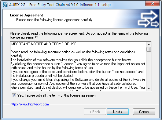
(HighTec 설치 진행 중 UDEVisualPlatfrom 과 CDM Driver Package HighTec 가 설치됨)
-
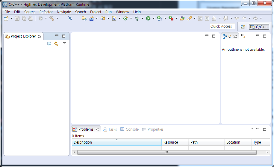
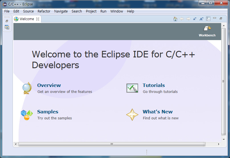
설치 완료 후 Eclipse.exe (C:\HIGHTEC\ide\eclipse-v1.6.1) , UDEVisualPlatfrom.exe (C:\Program Files (x86)\pls\UDE Starterkit 4.10) 실행 확인
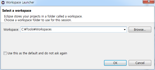
- Eclipse 실행화면 (Workspace는 defualt 값 사용)
BIFACES Installation
-
-
참고로 BIFACES_V1_0_2_Win64.exe 설치하여 사용하는 것도 가능하지만, Bifaces/eclipse/eclipse.ini 에서 자바가 설치된 디렉토리를 설정해주는 추가 작업 필요
-
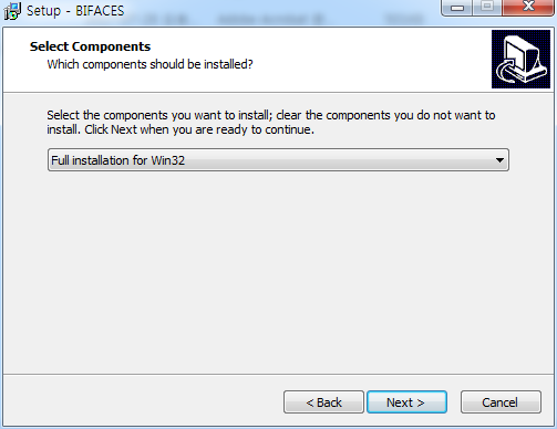
BIFACES_V1_0_2_Win32.exe 실행
-
Select Components 에서 Full installation 선택 후 설치 진행
-
- 설치 완료 후 StartBifaces.bat (C:\Tools\BifacesWin32) 파일을 실행
- .bat file 실행 화면 (Workspace는 defualt 값 사용)
SerialPlot Installation
-
SerialPlot 공식 홈페이지에 접속하여 다운로드 및 설치 진행하거나 아래 링크를 이용 (자신의 PC 운영체제에 맞게 설치)
- 64bit setup: https://bitbucket.org/hyOzd/serialplot/downloads/serialplot-0.9.0-win64.exe
- 32bit setup: https://bitbucket.org/hyOzd/serialplot/downloads/serialplot-0.9.0-win32.exe
-
설치 완료 후 serialplot.exe C:\Program Files\serialplot\bin 프로그램을 실행 확인
- SerialPlot 실행 화면

TeraTerm Installation
-
TeraTerm 공식 홈페이지에 접속하여 다운로드 및 설치 진행
-
Select Components 에서 Standard installation 선택 후 설치 진행

- 설치 완료 후 ttermpro.exe (C:\Program Files (x86)\teraterm) 실행 확인
- ttermpro.exe 실행 화면

Project Build
Project download and import
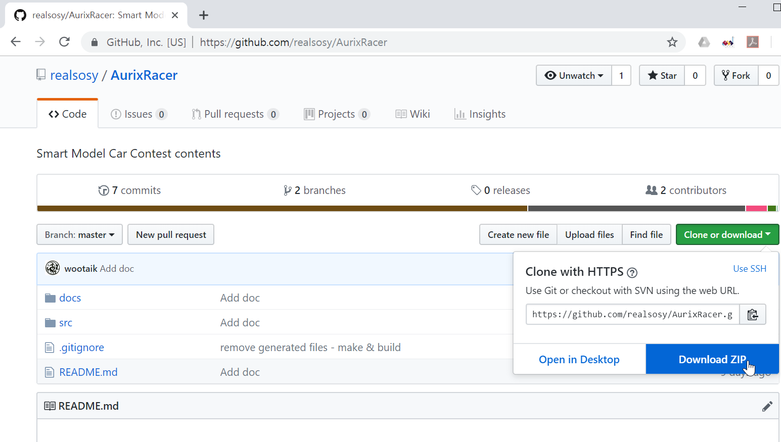
- AurixRacer 홈페이지 에서 Clone or download >> Download ZIP 클릭 후 AurixRacer-master.zip downloasd 후 압축 해제
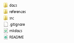
- 압축 해제한 폴더 확인
-
BIFACES 실행 (StartBifaces.bat (C:\Tools\BifacesWin32) 실행)
-
Workspace 설정
- 소스코드를 포함한 프로젝트를 관리 할 폴더 설정
- 새로 만든 Workspace에 src 폴더 (~\AurixRacer-master\src) 를 복사 또는 이동 하거나
- src 폴더를 Workspace로 지정
- 다운로드 받은 AurixRacer 프로젝트 Import
- File >> Import 클릭
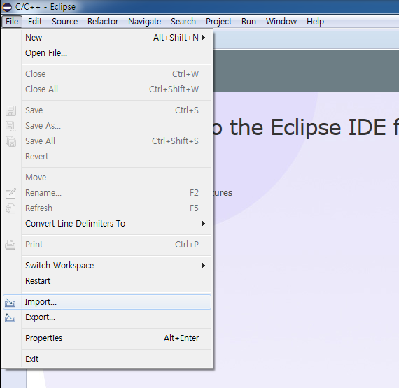
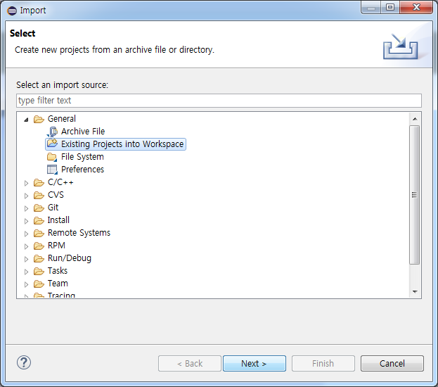
- General >> Existing Projects into Workspace 선택 후 Next > 클릭
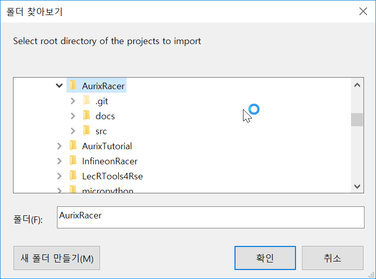
- Select root directory 에서 Browse... 클릭, Workspace의 src 폴더 선택 후 확인 클릭
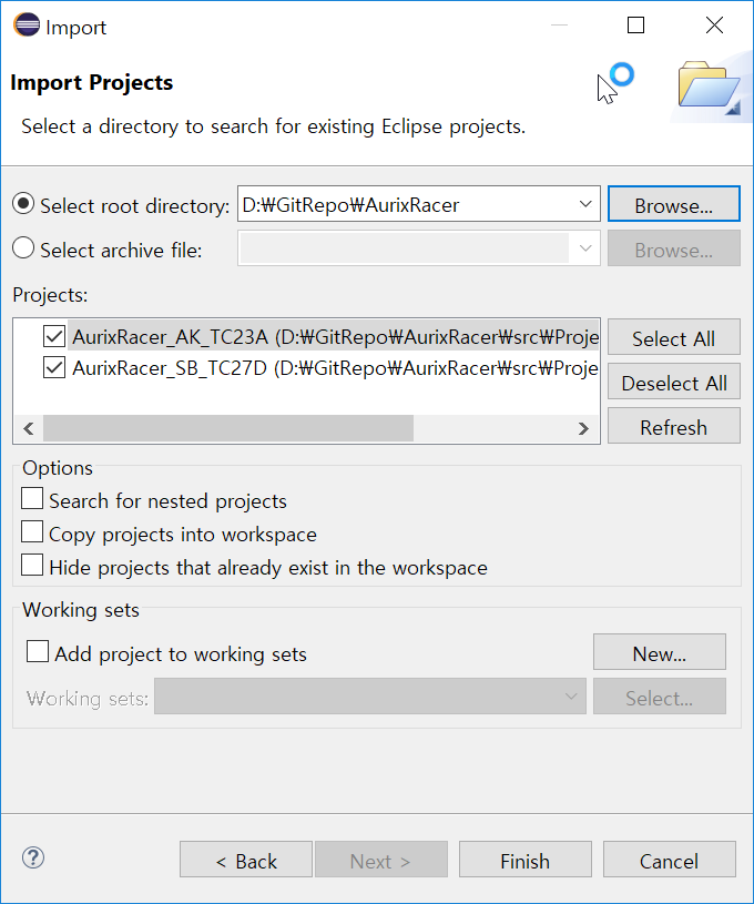
- Projects 탭에서 AurixRacer_TC27D 체크박스 선택 후 Finish 클릭
- 다른 프로젝트는 AurixRacer 에서 다루는 각각의 모듈기능 으로 나누어져 있음
- Project Explorer 를 통해 Import 된 프로젝트를 확인할 수 있음 (Welcome 창은 닫으면 됨)
Build
-
Build 전 Complier 설정
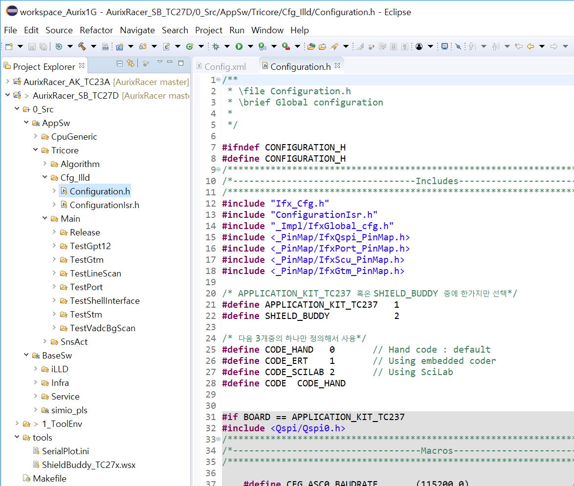
- Project explorer 창에서 AurixRacer_SB_TC27D >> 1_ToolEnv >> 0_Build >> 1_Config >> Config_Tricore_Gnuc 안에 있는 Config_Gnuc.mk 파일을 더블클릭 하면 편집 가능한 Edit창이 나옴
- Tricore toolchain의 경로 및 버전이 맞게 설정되어 있는지 확인
B_GNUC_TRICORE_PATH:= C:\HIGHTEC\toolchains\tricore\v4.9.1.0-infineon-2.0
-
Project explorer 를 통한 build
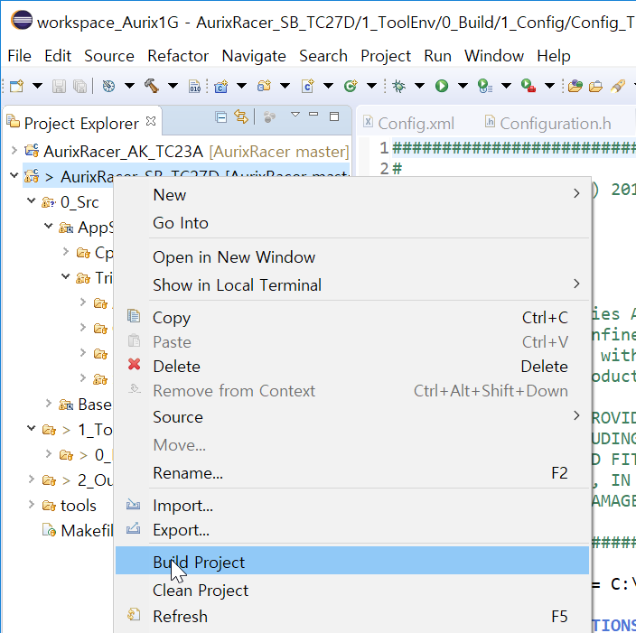
- Project Explorer 창에서 Build 할 프로젝트를 우클릭 한 뒤 Build Project 클릭
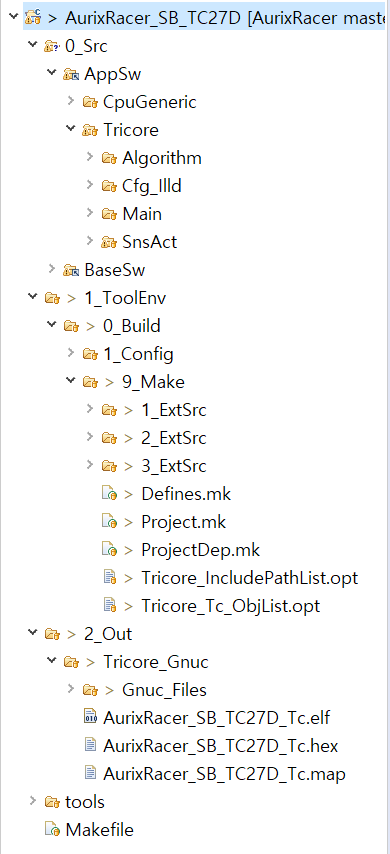
- Build 후 결과
- 0_Build 폴더에 9_Make 폴더 생성
- 2_Out 폴더 생성
- 2_Out/Tricore_Gnuc/Gnuc_Files 에 .elf 파일과 .hex 파일 그리고 .map 파일 생성
- Build error 발생시 추가사항 의 Build - Error181 참고
UDEVisualPlatfrom 을 이용해 실행 파일 버닝, TeraTerm 을 동작 확인
-
Build를 통해 생성한 elf 파일을 AppKit 에 다운로드 하고 TeraTerm을 이용해 Shell 환경 실행
-
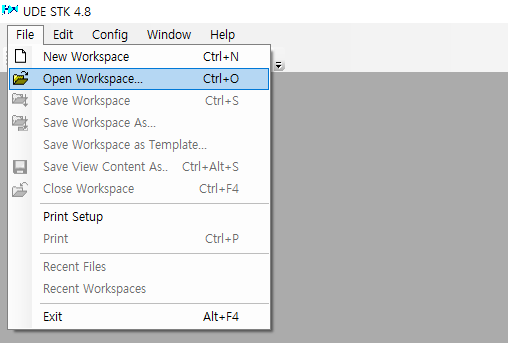
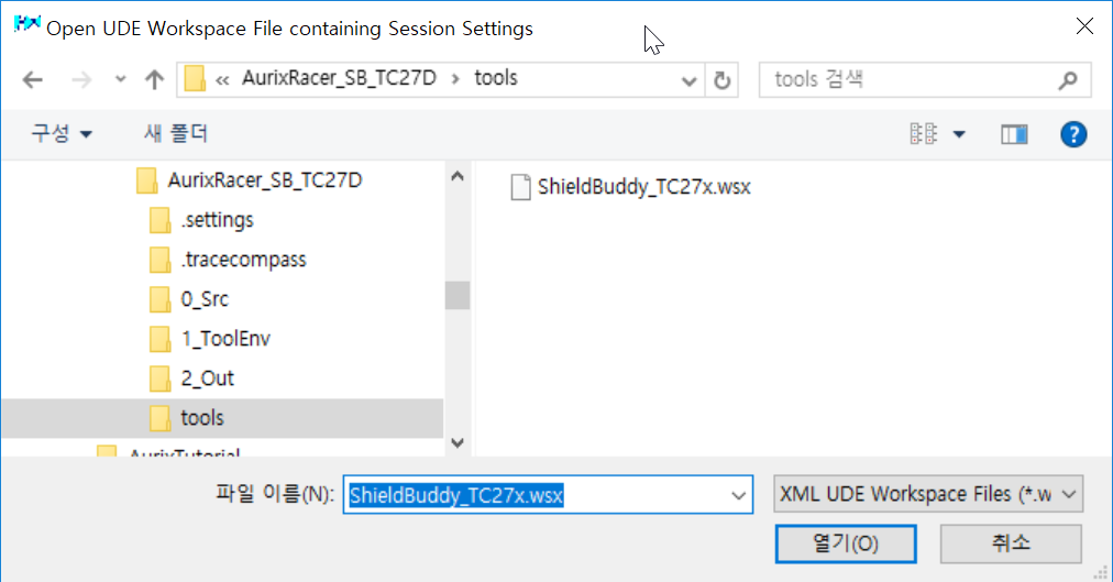
UDEVisualPlatfrom 을 실행하여 File >> Open Workspace... 클릭
- BIFACES Workspase/AurixRacer_SB_TC27D/tools/ShieldBuddy_TC27x.wsx 파일 열기 (BIFACES Workspase/AurixRacer_AK_TC23A/tools/AppKit_TC23x.wsx 파일 열기)
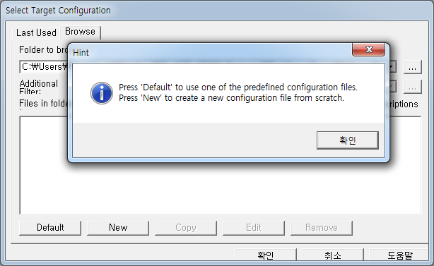
- 다음과 같은 창이 뜨면 확인 클릭 후 New 클릭
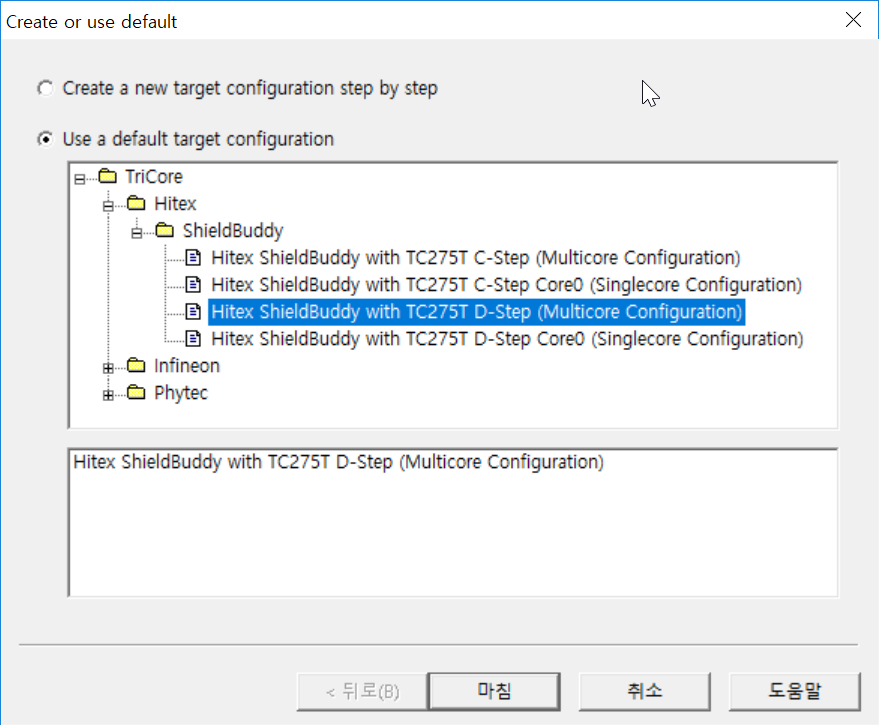
- Use a default target configuration 체크 후 하단의 폴더트리에서 TriCore >> Hitex >> ShieldBuddy >> Hitex ShieldBuddy with TC275T D-Step (Multicore Configuration) 선택 후 마침 클릭
-
*.cfg 파일 저장 후 확인 클릭
-
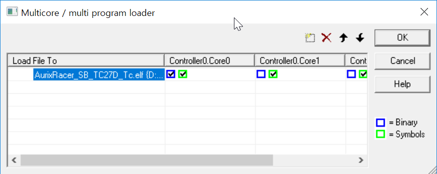
상단의 File >> Load Program 클릭 후 빌드한 Elf 파일 선택 (2_Out/Tricore_Gnuc/Gnuc_Files/AurixRacer_SB_TC27D_Tc.elf )
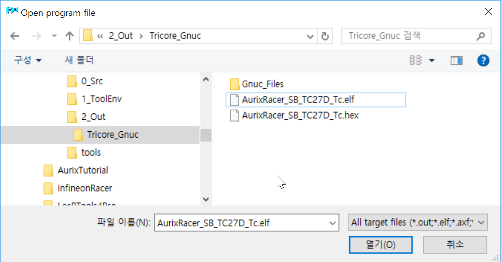
- Elf 파일 경로 확인 후 OK 클릭 (경로가 빌드 후 생성된 2_Out/Tricore_Gnuc/Gnuc_Files/AurixRacer_SB_TC23A_tc.elf 파일로 설정되어 있는지 확인)
- ShieldBuddy 를 USB로 Host PC와 연결한 후 File >> Connect Target System.. 클릭 (Host PC와 첫 연결 시 드라이버 다운로드가 진행됨)

- UDE - FLASH/OTP Memory Programming Tool 창에서 Program all 버튼 클릭
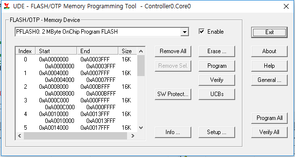
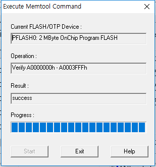
- Execute Memtool Command 창에서 Results: success 와 같이 뜨면 ShieldBuddy 에 프로그래밍이 완료됨, Exit 를 클릭하여 UDE - FLASH/OTP Memory Programming Tool 창과 Execute Memtool Command 창을 닫음
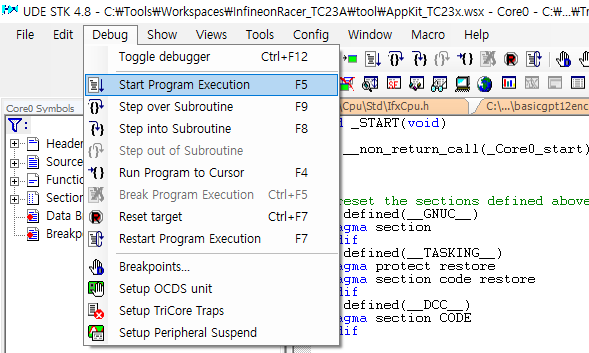
- Debug >> Start Program Execution 을 클릭하면 ShieldBuddy 에 다운로드 된 프로그램이 실행됨
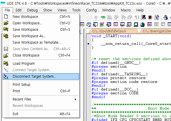
- File >> Disconnect Target System.. 클릭하여 Host PC와 ShieldBuddy 와의 연결을 해제
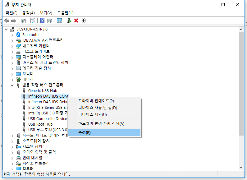
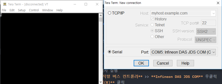
- COM port 활성화(첫 연결시 필요)
- 장치관리자 실행
- 범용 직렬 버스 컨트롤러 >> Infineon DAS JDS COM 우클릭 한 뒤 속성(R) 클릭
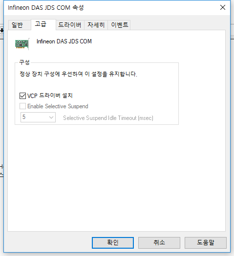
- 고급 탭에서 VCP 드라이버 설치 체크 후 확인 클릭
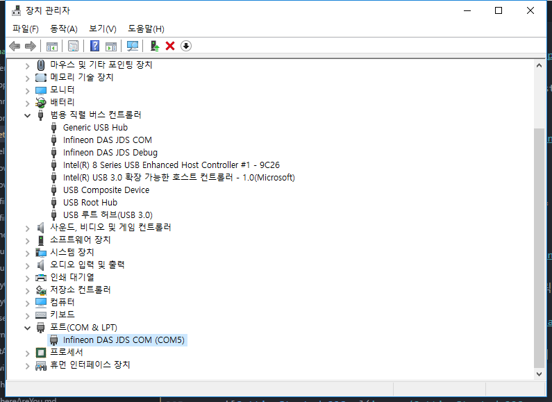
- ShieldBuddy 와 Host PC의 USB 연결을 분리했다가 재연결 한 뒤 장치관리자 에서 등록되는 COM port의 번호 확인 (재연결시 드라이버가 자동으로 설치됨)
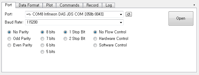
- TeraTerm 실행 후 Serial 체크, Port: 에 Infineon DAS COM (COMn) 선택 후 OK 클릭
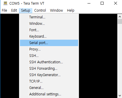
- Setup >> Serial port... 클릭
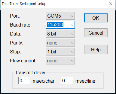
- Buad rate 을 115200 으로 설정하고 OK 클릭
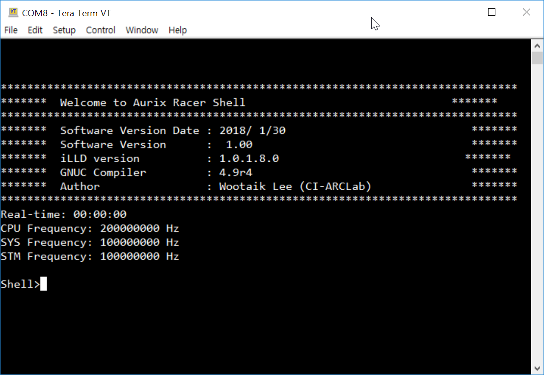
- TeraTerm VT 창에서 enter 를 입력하면 Shell> 이 화면에 나타남! 여기에 info 를 입력하고 enter를 입력하면 아래의 사진과 같이 Welcome to Aurix Racer Shell 확인 가능
Shell 을 이용한 동작 확인
-
Digital I/O, Analog I/O 장치의 동작 확인
-
DC motor, Servo, Encoder, Line scan camera등 주변 장치 동작 확인
- DC Motor Control Shield with BTN8982 , Servo 등과 ShieldBuddy 의 연결은 ConnectionGuide를 통해 확인 가능
기본적인 Shell 사용법
- Shell 은 사용자가 입력한 명령어를 해석하여 ShieldBuddy 가 동작할 수 있도록 해주는 역할을 함(자세한 내용은 MyOwnTerminal 참고)
-
명령어를 통해 AurixRacer 에서 제공하는 Peripheral 장치들을 제어하고 상태 확인 가능
-
help 명령어를 통해 사용가능한 명령어 확인 가능
Shell>help status : Show the application status m0v : Motor0Vol m1v : Motor1Vol m0e : Motor0Enable srv : Servo Angle srvscan : ServoScan Angle l0 : LED0 l1 : LED1 l2 : LED2 ls0 : LineScan0 ls1 : LineScan1 mls : Monitoring LineScan vadc : Vadc Backgound 1 enc : Encoder p00_0 : Port00_0 p00_1 : Port00_1 info : Show the welcome screen help : Display command list. -
특정 명령어셋의 사용법(syntax)을 확인하기 위해서는 "(명령어) ?"" 를 입력 후 enter를 입력한다.
Shell>p00_0 ? Syntax : p00_0 Shell>l0 ? Syntax : l0 0/1 Shell>vadc ? Syntax : vadc Shell>srv ? Syntax : srv frac-value Shell> -
상세한 내용은 MyOwnTerminal 문서와 AsclinShellInterface.c 코드 참고
LED
-
l0, l1, l2 명령어를 통해 ShieldBuddy의 DIG.40, DIG.38, DIG.36을 각각동작시킬 수 있다.
Shell>l0 ?
  Syntax     : l0 0/1
Shell>l0 0
  Led0:    0    # DIG.40 LOW
Shell>l1 1
  Led1:    1    # DIG.38 HIGH
Shell>l2 0
  Led12:   0    # DIG.36 LOW
DC motor
-
m0v, m0e 명령어를 이용해 모터 제어와 상태 확인 가능
- frac_value: -1.0 ~ 1.0
Shell>m0e ?
  Syntax     : m0e 0/1
Shell>m0e 1                     # DC motor 동작 가능하도록 설정
  Motor0En:    1
Shell>m0v ?
  Syntax     : m0v frac-value
Shell>m0v -0.2                   # Motor에 인가되는 전압을 제어
  Motor0Vol: -0.20 fraction
Servo
-
srv 명령어를 입력해 동작 확인이 가능
- frac_value: -1.0 ~ 1.0
Shell>srv ?
  Syntax     : srv frac-value
Shell>srv 0.5
  SrvAngle: 0.50 fraction
Shell>srv -0.5
  SrvAngle: -0.50 fraction
Line scan camera
-
Line scan camera는 2개의 채널을 제공하며 각각 ls0 , ls1 명령어를 통해서 값 확인이 가능
Shell>ls0 ? Syntax : ls0 Shell>ls0 LineScan0 results 1752, 1752, 1734, 1738, 1742, 1745, 1748, 1748, 1748, 1750, 1750, 1749, 1749, 1749, 1748, 1747, 1747, 1746, 1730, 1737, 1742, 1744, 1747, 1748, 1750, 1749, 1751, 1750, 1751, 1752, 1752, 1752, 1751, 1734, 1738, 1743, 1745, 1747, 1748, 1750, 1749, 1750, 1751, 1751, 1751, 1752, 1752, 1733, 1738, 1740, 1742, 1742, 1743, 1744, 1744, 1746, 1747, 1749, 1751, 1751, 1752, 1752, 1733, 1719, 1730, 1736, 1741, 1744, 1747, 1748, 1748, 1748, 1748, 1747, 1747, 1746, 1746, 1746, 1746, 1746, 1746, 1747, 1745, 1746, 1746, 1746, 1748, 1749, 1751, 1751, 1752, 1751, 1750, 1733, 1720, 1710, 1704, 1700, 1697, 1695, 1694, 1693, 1692, 1691, 1692, 1691, 1692, 1690, 1689, 1690, 1690, 1690, 1690, 1690, 1690, 1712, 1721, 1730, 1738, 1743, 1746, 1748, 1750, 1748, 1748, 1747, 1746, 1746 Shell>ls1 LineScan1 results 1753, 1754, 1753, 1735, 1739, 1741, 1743, 1744, 1746, 1746, 1746, 1747, 1747, 1747, 1748, 1748, 1748, 1748, 1749, 1748, 1750, 1752, 1752, 1753, 1753, 1753, 1752, 1752, 1753, 1754, 1753, 1754, 1754, 1752, 1751, 1752, 1753, 1753, 1753, 1754, 1754, 1753, 1751, 1753, 1754, 1754, 1756, 1755, 1754, 1735, 1741, 1745, 1747, 1750, 1750, 1751, 1752, 1750, 1748, 1753, 1754, 1755, 1754, 1753, 1752, 1752, 1752, 1753, 1753, 1754, 1754, 1755, 1752, 1753, 1754, 1754, 1755, 1755, 1753, 1751, 1751, 1750, 1750, 1749, 1749, 1749, 1749, 1751, 1756, 1752, 1753, 1755, 1753, 1752, 1735, 1739, 1743, 1746, 1749, 1752, 1751, 1752, 1751, 1748, 1749, 1749, 1748, 1748, 1748, 1748, 1748, 1748, 1747, 1748, 1748, 1748, 1750, 1752, 1752, 1753, 1753, 1753, 1754, 1735, 1722, 1732, 1737, 1743 -
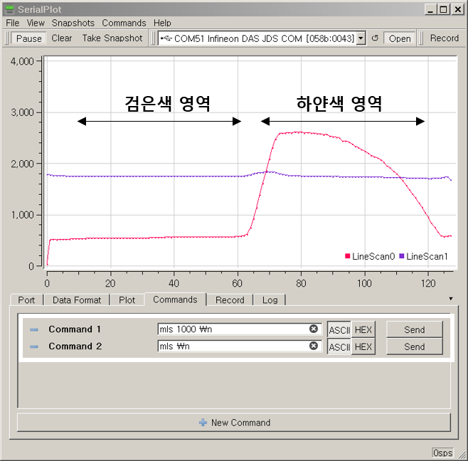
SerialPlot 프로그램을 이용해 실시간 값 확인 가능
- mls 명령어를 통해 주기적으로 line scan camera의 값을 받아올 수 있음
``` Shell>mls ? Syntax : mls period_ms Shell>mls 100 # 100msec 주기로 line scan camera 값을 불러옴 mls: 100 Shell> 1749, 1752 1749, 1753 1750, 1753 1732, 1752 1745, 1743 1748, 1747 1749, 1749 1751, 1750 1750, 1751 1750, 1752 1750, 1753 1750, 1753 (...)
```
-
SerialPlot 을 실행하고 아래 이미지와 같이 포트 설정 후 Open 클릭
- 아래와 같이 Command 를 입력하고 Send를 입력하면 실시간으로 Line scan camera의 raw 데이터 확인 가능(LineScan0 만 사용)
Encoder
-
enc 명령어를 통해 동작 확인이 가능
Shell>enc ?
  Syntax     : enc
Shell>enc
  Encoder speed: 1610612736, position: -1060059186, direction: 0
Shell>enc
  Encoder speed: 1073741824, position: -1059935370, direction: 0
Shell>enc
  Encoder speed: 1073741824, position: -1060233742, direction: 0
Shell>enc
  Encoder speed:     0, position: -1060724977, direction: 0
Digital I/O
-
P00_0 과 P00_1 에 연결되어있는 Digital 신호를 읽어옴
Shell>p00_0 ?
  Syntax     : p00_0
Shell>p00_0
  Port00_0:    0
Shell>p00_1 ?
  Syntax     : p00_1
Shell>p00_1
  Port00_1:    1
추가적인 설명
Build error - php.exe 실행 문제
- 빌드시 컴파일을 위한 Make 파일 생성이 안될 경우 빌드 에러 발생
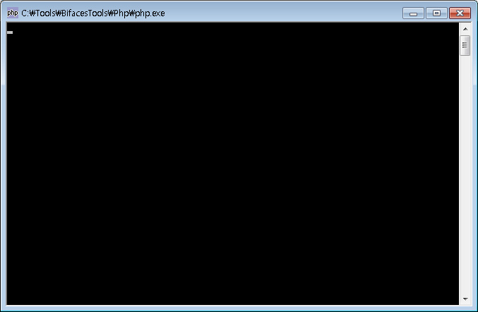
- BIFACES 가 설치된 경로에서 C:\Tools\BifacesTools\Php 로 이동하여 php.exe 실행
- 정상적으로 실행 되었을 때
- php.exe 파일이 실행은 되지만 아래 사진과 같이 에러가 발생
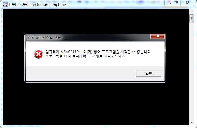
* [msvcr110.dll 파일을 다운로드](https://drive.google.com/open?id=1PNwUwMD-6SpE53mg-y7Iv8WzPXUfSWsH)
* 다운 받은 파일을 *C:\Windows\SysWOW64* 폴더(운영체제 Windows 64bit 기준)에 저장
* 다시 php.exe 파일을 실행하여 실행이 되는지 확인 (정상적으로 실행이 되면 검은 도스창이 뜬다) 후 다시 빌드 실행
- php.exe 파일이 실행되지 않을 경우

* 설치된 백신 프로그램(ex. 알약)을 종료시키고 **BIFACES** 를 다시 설치
* 다시 *php.exe* 파일을 실행하여 실행이 되는지 확인 후 다시 빌드 실행